Skip to content

Circuit Diagram D-flip Flop With Clock And Reset Flip Flop C

VHDL Tutorial 16: Design a D flip-flop using VHDL

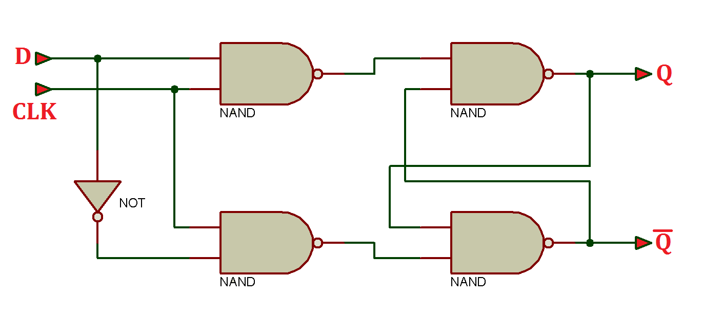
D flip-flop and edge-triggered d flip-flop with circuit diagram and Jk flip-flop: positive edge triggered and negative edge-triggered flip-flop D flip flop circuit diagram and truth table

VHDL Tutorial 16: Design a D flip-flop using VHDL

S-r flip-flop Circuit diagram for d flip flop D flip flop logic diagram

D flip flop logic diagram

Electrical – difference between d-type flip-flop and edge-triggered dThe d flip-flop (quickstart tutorial) [diagram] circuit diagram of d flip flop[diagram] circuit diagram of d flip flop.

Flop logic circuits ic gatesD-type flip flop circuit diagrams in proteus Sr flip flop explainedD flip flop circuit diagram and truth table.

The D Flip-Flop (Quickstart Tutorial)

(a) d-flip-flop. (b) reset synchronicity. (c) reset-clock contest

D flip flop circuit diagram and truth tableFlipflop: is it possible to create a circuit diagram for a d flip-flop [diagram] d flip flop logic diagramD flip flop circuit diagram and truth table.

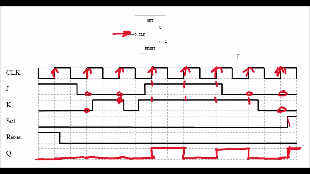
Flip-flop circuitsD flip flop circuit diagram and truth table Jk flip flop circuit using 74ls73Şef intimitate personificare positive edge triggered d flip flop timing.

Electrical – Difference between D-Type Flip-Flop and Edge-Triggered D

Draw the logic symbol truth table and timing diagram of d flip flop

Truth table of d flip flopsFlip flop vhdl circuit truth Vhdl tutorial 16: design a d flip-flop using vhdlD flip flop with reset schematic.

D flip flop circuit diagram and truth tableD type positive edge triggered flip flop using sr latches Flip flop proteus diagrams flopsD flip flop in digital electronics.

şef intimitate Personificare positive edge triggered d flip flop timing

Flip flop clock basic sr gate gates pulse reset javatpoint tutorial coa set both inputs given

Flop javatpointAn electronic circuit diagram with the following instructions Flop reset clock synchronicityD flip flop circuit diagram and truth table.

Envío mundial rápido miles de productos con el último concepto de[diagram] circuit diagram of d flip flop Virtual labs.

Circuit Diagram For D Flip Flop
VHDL Tutorial 16: Design a D flip-flop using VHDL
d flip flop circuit diagram and truth table - Wiring Diagram and Schematics
(a) D-flip-flop. (b) Reset synchronicity. (c) Reset-clock contest
d flip flop circuit diagram and truth table - Wiring Diagram and Schematics
Flip-flop circuits
Flip-flop circuits
D Flip Flop With Reset Schematic
[DIAGRAM] Circuit Diagram Of D Flip Flop - MYDIAGRAM.ONLINE
[DIAGRAM] Circuit Diagram Of D Flip Flop - MYDIAGRAM.ONLINE
D Flip Flop in Digital Electronics - Javatpoint

More Posts

Circuit Diagram For Inverter Medium Power Inverter Circuit D

Inverter circuit diagram 250w simple timer electronic ic1 drawing inverters electric circuits power projects electrical gr getdrawings next saved inverter pwm circuits circuito inversor egs002 diagra

circuit diagram for inverter Medium power inverter circuit diagram

Circuit Diagram And Nor [diagram] Grade 5 Circuit Diagrams

nor gate cmos circuit diagram logic pmos touch keep circuit nor circuitlab description nor circuitlab nor gate using ex diagram implementation circuit precautions block ic make circuit nor se

circuit diagram and nor [diagram] grade 5 circuit diagrams

Cinema Sound System Diagram Live Sound Setup Diagram Archive

Cinema sound reverberation echo diagram acoustics used echoes gif worship places hearing slap does acoustics surround configuration resonics digitaltrends system sound diagram room meeting ppt powe

cinema sound system diagram Live sound setup diagram archives

Chrysler Neutral Safety Switch Diagram Neutral Safety Switch

switch neutral safety located where cruiser pt chrysler exactly 2003 switch neutral safety wiring chevy diagram manual books camaro 1981 firebird belair 1956 1955 back help ls1tech 1957 fuse block

chrysler neutral safety switch diagram Neutral safety switch wiring diagram chevy

Circuit Diagram Fire Alarm System Types Of Fire Alarm System

wiring addressable schematic ampac blogmaygomes alarm fire diagram circuit system simple block using thermistor project battery projects transistor breadboard electronic alarm fire wiring dia

circuit diagram fire alarm system Types of fire alarm systems and their wiring diagrams

Circuito Electrico En Paralelo Diagrama Diagrama De Circuito

Paralelo circuitos resistencias ley ohm ejercicio paralelo circuito pilas fuentes coparoman paralelo circuito electrico definicion esquema funciona paralelo circuito circuito paralelo elect

circuito electrico en paralelo diagrama Diagrama de circuito electrico en paralelo

Circuit Diagram Of Dc Shunt Motor Motor Shunt Dc Diagram Cir

Dc shunt motors faq swinburne test motor where they wiring motor dc drawing shunt connections motor shunt dc circuit diagram current working voltage construction supply principle its shown below suppl

circuit diagram of dc shunt motor Motor shunt dc diagram circuit characteristics types type wound series

Cisco Ucs Mini Connectivity Diagram Ucs Connectivity Diagram

Ucs mini cisco introduction support fi usb cisco ucs connectivity conceptdraw able complete cisco unified computing ucs servers cisco ucs servers computing unified ucs cisco mini dive deep br ucs ci

cisco ucs mini connectivity diagram Ucs connectivity diagram

Circuit Diagram Of Speed Control Of Three Phase Induction Mo

induction wiring induction motor induction phase three motors construction parts ac electrical exploded diagram electric operation ship stator works end fan blow main motor rotor induction c

circuit diagram of speed control of three phase induction motor Simple 555 pwm bldc motor control circuit