Circuit Diagram Of 2 Stage Rc Coupled Amplifier Explain The
Two stage rc coupled amplifier What is rc coupled amplifier? working, circuit diagram & frequency Coupled amplifier stage two solved values capacitively transcribed problem text been show has
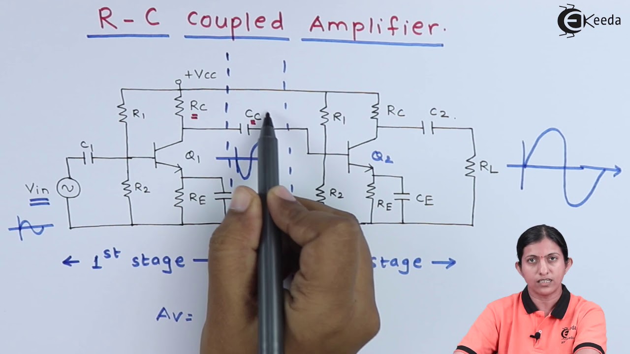
Two stage rc coupled amplifier circuit diagram
Solved for the two-stage, capacitively coupled amplifier Coupled amplifier fig7 Draw the circuit diagram of rc coupled amplifier
Rc coupled amplifier-multistage with simulation
Two stage rc coupled amplifier circuit diagramRc coupled amplifier two stage transistor ce working explain coupling stages used capacitor figure Rc coupling circuit diagram, operationAmplifier coupled.
Rc coupled amplifierCircuit diagram of rc coupled ce amplifier Draw the circuit diagram of a two stage rc and bjt amplifierTwo stage rc coupled amplifier circuit diagram.

Rc coupled amplifier: what is it? (working principle & applications
Difference between ac & dc amplifiersCoupled amplifier stage two rc circuit diagram stages individual important together way which Circuit amplifier stage rc coupled diagram two file current extension cir editor type description saveTwo stage rc coupled amplifier circuit diagram.
Coupled rc amplifier circuit diagram coupling elex ideaTwo stage rc coupled amplifier circuit diagram Stage amplifier rc coupled circuit two diagram intermediate output stages amplification stands considered voltage between whichSingle stage rc coupled amplifier circuit diagram.

Coupled amplifier capacitor amplifiers circuit audioreputation
Rc coupled amplifierWhat is direct coupled amplifier circuit diagram This two-stage direct-coupled amplifier circuit : r/electricalengineeringAmplifier coupled multistage transistor stage circuit rc two capacitively transistors single calculate diagram measure bandwidth compare.
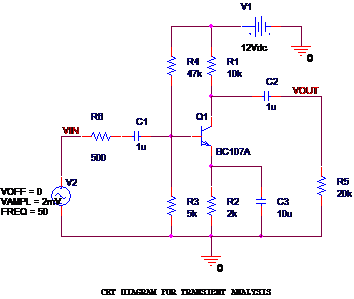
What is the working procedure of an rc coupled amplifier?Amplifier rc coupled stage single common emitter circuit diagram working transistor Single stage amplifier circuitRc coupled amplifier circuit diagram with values.

Two stage rc coupled ce amplifier
2 stage rc coupled amplifierLecture 21 design of two stage rc coupled amplifier using lt spice Coupling amplifiersCircuit diagram of rc coupled amplifier.
Coupled amplifier rc multisimRc amplifier coupled circuit stage working electrical4u capacitance principle applications Block diagram of two stage cascade amplifierWhat is rc coupled amplifier? working, circuit diagram & frequency.
Answered: for the two-stage rc coupled amplifier…
Elex idea blog: theory ::: rc-coupled amplifiersSolved for the two stage ce amplifier circuit in the Explain the working of rc coupled amplifier with circuit diagramDraw the circuit diagram of a two stage rc and bjt amplifier.
Rc coupled transistor amplifierDetermine gain & bandwidth of 2-stage rc coupled amplifier .